OE-CC3022T5 Installation Guide
PRECAUTIONS
- The camera must not be installed in a location that is exposed to heavy vibration or possible impacts.
- The camera should be used in compliance with local laws and regulations.
- Do not install the camera on an unstable mount or surface.
- Do not disassemble the camera or perform maintenance when power is connected.
- Before installation, the camera should be stored in a dry and ventilated environment.
- Use only accessories that comply with the technical specifications of the camera.
Follow the Quick Start Guide for installing an OpenEye cloud camera and adding it to OpenEye Web Services.
CONTENTS
OE-CC3022T5 cameras come with a mounting template, desiccant pack, adapter plate, screws, screw anchor mounts, torx tool, and waterproofing kit. Identify the following components to make sure everything has been properly included with your new camera. If any of the following items are missing, contact the dealer to arrange a replacement.
|
Turret Camera |
Mounting Template |
|
Desiccant Pack |
Adapter Plate |
|
x3 Philips 1-3/8" 35mm Screw |
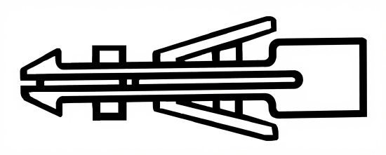
Screw Anchor Mounts |
|
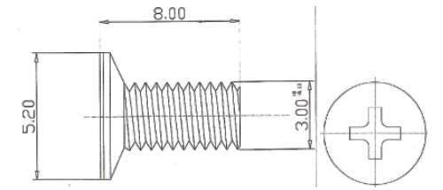
x3 Philips M3 x 8mm |
x3 Philips M4 Head, M3 x 8mm |
|
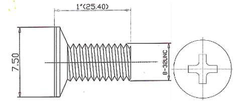
x4 Philips #6-32, 1" |
x4 Philips #8-32, 1" |
|
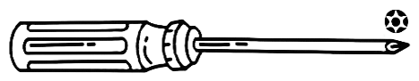
T10 Torx Tool |
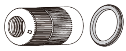
Waterproof Cable Connector |


Adapter Plate Compatibility

| B | Double Gang Electrical Box |
| C | 4" Round Electrical Box |
| D | OE-CA30PC-01 |
| E | OE-CA30JB-01 |
| F | OE-CA30WM-01 |
Hardware Installation
|
1. Attach the positioning sticker to a wall or ceiling, then drill screw holes and cable holes according to the positions marked on the positioning sticker.
|
2. Attach the adapter plate to the mounting surface (F holes) or mounting accessory (C-F holes) using the provided screws.
|
|
3. Open the camera cover.
|
4. Route the cables through the routing hole.
|
|
5. Insert the network cable and grommet into the camera base.
|
6. Connect the network cable to position 2 (if you are not using PoE for power, connect the DC12V power at position 1-1), and secure the base of the camera to the adapter plate by tightening the 3 torx screws (as seen in step 5).
|
|
7. Adjust the camera field of view once online and reattach the camera cover to the base of the camera.
|
|


