OE-C9912M20 Quick Installation Guide
Click the link if you need to download the original hardcopy of the OE-C9912M20 Quick Installation Guide included with the boxed contents.
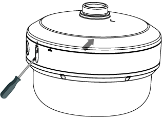
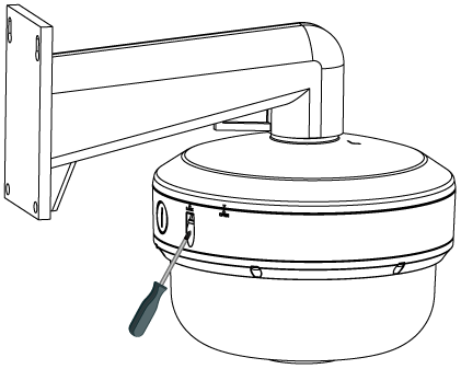
Preparing the Camera
- Loosen the 6 screws to remove the bottom cover.

- Remove and discard the protective EPE from the lens module.

EPE
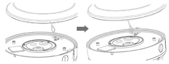
- Remove the desiccant packet from its package. Peel away the protective paper to expose the adhesive strip and install the desiccant in the recommended position with the adhesive strip down.

- Attach the spring cable and tighten the 6 screws to secure the cover.

Wall Mount Installation
- Loosen the anti-drop screw on the lateral side of the bottom cover.
- Rotate the cap
 from LOCK to OPEN in order to remove the cap.

- Disconnect the safety wire from the hook.

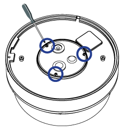
- Loosen the 3 screws on the bottom plate and open it.
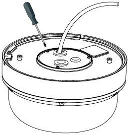
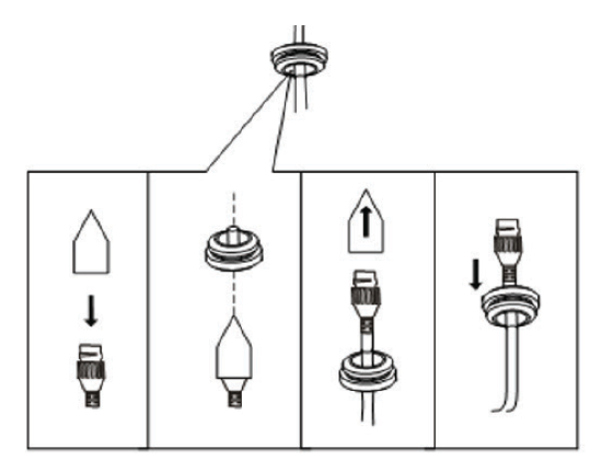
- Route the network and applicable I/O cables through the grommets.


- Reinstall the bottom plate and tighten the 3 screws.
- Thread the pendant cap onto the wall mount arm and tighten the set screw.

- Reconnect the safety wire.
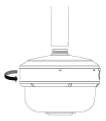
- Rotate the camera from OPEN to LOCK in order to fix the camera. The mark should be aligned with the LOCK
 mark.
mark.

- Tighten the screw on the lateral side of the bottom cover.
Pendant Mount Installation
- Loosen the anti-drop screw on the lateral side of the bottom cover.
- Rotate the cap from LOCK to OPEN in order to remove the cap.

Disconnect the safety wire from the hook.

- Loosen the 3 screws on the bottom plate and open it.

- Route the network and applicable I/O cables through the grommets.

- Reinstall the bottom plate and tighten the 3 screws.

- Reconnect the safety wire.

- Thread the pendant cap onto the pendant mount and tighten the set screw.

- Rotate the camera from OPEN to LOCK in order to fix the camera. The mark should be aligned with the LOCK mark.
- Tighten the screw on the lateral side of the bottom cover.

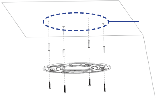
Ceiling Mount Installation
- Apply the provided template sticker to the desired installation location. With a 3/16" drill bit, drill the marked holes for the screw anchors. Remove the template sticker and insert the plastic screw anchors.
- Loosen the 4 screws on the plate.
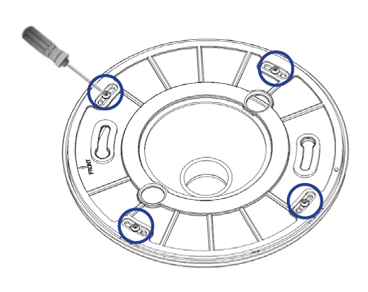
- Secure the plate to the ceiling using the included screws.

- Loosen the 3 screws on the bottom plate and open it.
- Route the network and applicable I/O cables through the grommets.
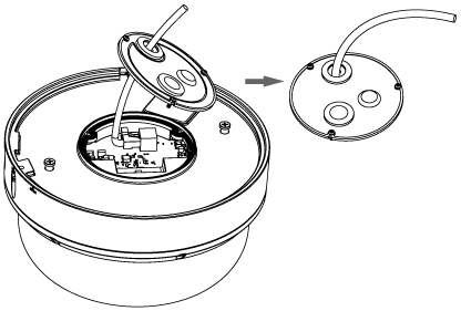

- Reinstall the bottom plate and tighten the 3 screws.
- Connect the safety wire.

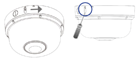
- To attach the camera to the plate, twist the camera counterclockwise until it is secured firmly in place. Then tighten the screw on the lateral side of the bottom cover.
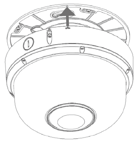
NOTE: Please note that the OPEN  mark should be aligned with the screw hole on the plate (There is only 1 screw hole on the plate for easy recognition).
NOTE: The camera can be mounted to a 4" electrical box when used with the mounting plate.